説明書 ソニー VCT-VPR10 三脚
ソニー VCT-VPR10 三脚 のマニュアルが必要ですか? 以下では、日本語の PDF マニュアルを無料で表示およびダウンロードできます。 この製品には現在、0 件のよくある質問、0 件のコメントがあり、0 件の投票があります。 これがご希望のマニュアルではない場合は、お問い合わせください。
ご利用の製品に欠陥があり、マニュアルでは解決出来ない問題ですか。無料の修理サービスを行うRepair Café (Repair Café) に移動します。
説明書
Loading…
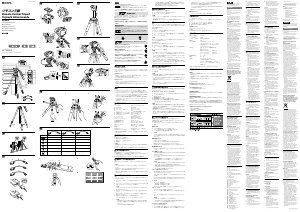
マルチ端子用接続ケーブルを図
ˎ
(d)
の形状の本体のマルチ端子にさ
すときは、本体のマルチ端子「」とマルチ端子用接続ケーブルプラ
グ部の「」をあわせて挿入してください。
逆方向に無理に差し込むと、故障の原因になります。
高さを調節する
1
エレベーターストッパーを緩める。
2
カメラ台を上下に動かし、適当な高さに合わせる。
3
エレベーターストッパーを締める。
ご注意
エレベータストッパーを緩める際は、カメラ台が急に下がらないよう手
ˎ
で支えながら行って下さい。
高さ調節後、エレベータストッパーは確実に締め付けて下さい。
ˎ
パンニング/ティルティング
エレベーターストッパーがしっかり締まっているか確認してから、パンニ
ング/ティルティングは行ってください。締めかたが充分でないと、画像
がゆれる原因になります。
パンニング
カメラを
360
°回転させて撮影することができます。
1
パンストッパーを緩める。
2
パンハンドルを左右方向の希望の位置に動かし、カメラ位置を調節す
る。
3
パンストッパーを締める。
ご注意
急にパンニングした場合、カメラネジが緩むときがあります。緩んでいな
いか、ときどき確認してください。
ティルティング
カメラを上下に向けて撮影することができます。
4
ティルトストッパーを緩める。
5
パンハンドルを上下方向の希望の位置に動かし、カメラ位置を調節す
る。
6
ティルトストッパーを締める。
ご注意
この三脚はローポジション対応のためエレベータが
2
つに分かれてい
ˎ
ます。エレベータ
A
とエレベータ
B
の接続部分を本体より上にあげ、パン
ロックした状態で反時計回りにパンニングし続けると、エレベータ
B
か
らエレベータ
A
が外れます。
エレベータを上げてパンニングするときはエレベータ
A
とエレベータ
B
をしっかり締め、必ずパンロックを緩めてご使用下さい。
パンストッパーやティルトストッパーをトルクの重さ調整には絶対に
ˎ
使用しないでください。故障の原因となります。確実にストッパーを緩
めてから、パンニング、ティルティングをしてください。
カメラ台の位置を変える
カメラの縦位置撮影ができます。
パンストッパーを緩めカメラ台を右側へ起こし、パンハンドルパンストッ
パーを締める。
ご注意
カメラの重心位置によっては任意の位置で固定できない場合や三脚が
ˎ
不安定になる場合があります。
カメラ台を起こしたり戻したりする際は、カメラに衝撃がかからないよ
ˎ
うゆっくり行って下さい。
位置を変えたあとはパンハンドルストッパーを確実に締め付けてくだ
ˎ
さい。
パンハンドルストッパーを緩めすぎるとパンハンドルが外れる場合が
ˎ
ありますのでご注意ください。
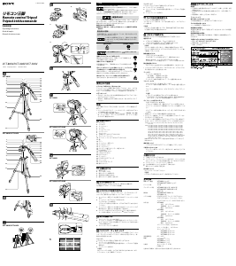
開脚角度の設定方法
脚角度ストッパーを上げることにより、脚角度を
23
度
/50
度
/75
度に調節
することができます。
ローポジション/セミローポジションにするには
1
ローポジションでエレベーターが地面に当たる場合はあらかじめエレ
ベーターBを取り外す。
2
脚を少し閉じる。
3
脚角度調節ボタンを押す。
4
脚角度調節ボタンを押したまま脚を広げる。
5
希望の角度になったら脚角度調節ボタンを放し、脚角度ストッパーが
元の位置に下がるまで脚を少し閉じる。
ご注意
最初に脚を少し閉じないと脚角度調節ボタンが固くて動かない場合が
ˎ
あります。また、脚角度調節後はストッパーに脚が当たる位置まで確実
に脚を広げてください。
脚角度調節ボタンはボタンの全面を押してください。
ˎ
ローポジションとセミローポジションでご使用になられるときは、脚を
ˎ
伸ばすと強度が十分取れませんので脚は伸ばさないでご使用下さい。
ローポジションの際はリモコンが地面に当たらないよう注意してご使
ˎ
用下さい。
リモコンで操作する
お手持ちのカメラの取扱説明書もあわせてお読みください。
ご使用になるケーブルによって操作できるボタン/スイッチ/ランプの
対応が異
なります(
A
)。
〇:有効(ご注意・カメラによっては対応していない場合もあります)
×:無効
電源を入れる
1
カメラの電源を入れ、スタンバイ状態にする。
リモコンの
POWER/REC
ランプ
(e)
が緑色に点灯します。
2
カメラを動画または静止画の状態にする。
ご注意
スタンバイ状態がしばらく続くと、自動的に電源が切れます。再び、ス
タンバイ状態にするには、リモコンの
POWER
ボタン
(a)
を押して電源
を入れます。
動画を撮影するには
START/STOP
ボタン
(c)
を押す。
POWER/REC
ランプが赤色に点灯して、撮影が始まります。
撮影を止めるには、もう一度
START/STOP
ボタンを押す。
POWER/REC
ランプが緑色に点灯して、スタンバイ状態になります。
静止画を撮影するには
PHOTO
ボタン
(b)
を半押ししてピントを合わせてから、止まるまで押
し込む。
ロック機構について(
B
)
バルブ撮影や連続撮影をするとき、
PHOTO
ボタンを押した状態を保持
することができます。
PHOTO
ボタンを深く押し込んだまま押し込んだまま、矢印の方向にス
ライドさせる。
バルブ撮影時はロックしている間、シャッターが開いています。
ˎ
連続撮影時はロックしている間、シャッターが切れ続けます。
ˎ
ご注意
バルブ撮影や連続撮影は全てのカメラで対応しているわけではあり
ˎ
ません。詳しくはカメラの取扱説明書をご参照ください。
故障の原因となる場合がありますので
PHOTO
ボタンを強く押し込
ˎ
んだり、強くスライドさせないでください。
ロック状態のまま放置しないでください。
ˎ
リモコンの取りはずしについて(
C
)
静止画を撮影するときは、リモコンを取りはずして
PHOTO
ボタンを押
すと、ブレを防止することができます。
PUSH RELEASE
ボタン
(f)
を押し、片手で三脚を抑えながら、リモコンを
引き抜く。
リモコンを取り付ける際は、三脚を抑えながら
PUSH RELEASE
ボタン
(
f
)がカチッと音がするまでリモコンをゆっくり挿し込んでください。
ズームする
ズームレバー
(d)
を傾ける。
T
側(望遠):
被写体が大きく写る。
W
側(広角):
被写体が小さく写る。
ズームレバーを傾ける角度によって、ズーム速度が変わります。
スローズームする
SLOW ZOOM
スイッチ
(h)
を「
ON
」にする。
ズームレバーを傾ける角度に関係なく、ズームは遅い速度に固定され
ます。
スローズームを解除するには、
SLOW ZOOM
スイッチを「
OFF
」にす
る。
ご注意
スローズームの速度はカメラにより異なります。
ˎ
POWER/REC
ランプが赤色に点滅した場合は、画面に警告表示が出
ˎ
ています。カメラの表示を確認してください。
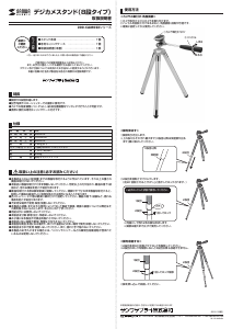
グリッドラインを表示させる(
D
)
GRID LINE
ボタン
(g)
を押す。
カメラの画面に水平・垂直のグリッドラインが表示されます。グリッ
ドラインに合わせて三脚の脚やティルティングを調節してください。
リモコン三脚
Remote Control Tripod
Trépied à télécommande
4-452-079-01(1)
取扱説明書
Operating Instructions
Mode d’emploi
Bedienungsanleitung
Manual de instrucciones
Gebruiksaanwijzing
VCT-VPR10
©2013 Sony Corporation Printed in China
お買い上げいただきありがとうございます。
電気製品は安全のための注意事項を守らないと、火災や人身事故に
なることがあります。
この取扱説明書には、事故を防ぐための重要な注意事項と製品の取り扱いかたを示
しています。この取扱説明書をよくお読みのうえ、製品を安全にお使いください。
お読みになったあとは、いつでも見られるところに必ず保管してください。
安全のために
ソニー製品は安全に充分配慮して設計されています。しかし、まちがった
使いかたをすると、火災などにより人身事故になることがあり危険です。
事故を防ぐために次のことを必ずお守りください。
●安全のための注意事項を守る
●故障したら使わずに、お買い上げ店またはソニーの相談窓口に修理を依
頼する
警告表示の意味
取扱説明書では、次のような表示をしています。表示の内容をよく理
解してから本文をお読みください。
この表示の注意事項を守らないと、感電やその他の事故に
よりけがをしたり周辺の家財に損害を与えたりすることが
あります。
注意を促す記号
行為を指示する記号
下記の注意事項を守らないと、
けが
をすることがあります。
開脚してからカメラを取り付ける
脚を閉じたまま取り付けると、転倒してカメラを破損したり
けがの原因となることがあります。
積載カメラ重量を守る
制限重量を超えると、三脚が倒れたりしてけがの原因となること
があります。
各ロックつまみやレバーおよび脚ロックナット、カメラネジなど
の締め付けパーツは確実に締め付けて固定する
締め付けが弱いと、ずれたりはずれたりして、カメラの破損や人
にけがを負わせる原因となることがあります。
脚の出し入れ、エレベーターの操作には充分注意をはらう
指などをはさみ、思わぬけがをすることがあります。
使用上のご注意
カメラを取りはずすには
必ず、カメラを持ってはずしてください。クイックシュー固定レバーを緩
めると、クイックシューが自動的に三脚からはずれ、カメラが落下する恐
れがあります。
持ち運びについて
使い終わったら、
ˎ
カメラをはずし、脚を収納し、パンハンドルの
操作部を外側に向けてたたんでください。
カメラを取り付けたままで、持ち歩かないでください。
ˎ
お手入れについて
汚れたら、やわらかい布に中性洗剤溶液を含ませてふいてから、乾いた
ˎ
布でからぶきしてください。
海岸など、潮風の当たる所で使用したあとは、乾いた布でよくふいてく
ˎ
ださい。
特長
この三脚はカメラなどにお使いいただける、リモコン機能付き三脚です。
パンハンドルのリモコンで、ソニーの「マルチ端子」または「
A/V
リモー
ˎ
ト端子」または「
REMOTE
(リモート)端子」付きカメラを操作することが
できます。すべてのカメラに対応している訳
ではありません。対
応機種
については、
ホームページ、カタログ等をご確認ください。
リモコンには撮影の基本機能(電源の
ON/OFF
、動画撮影・静止画撮影、
ˎ
ズーム)のほか、スローズームの
ON/OFF
、グリッドライン表示の
ON/
OFF
機能があります。
油圧式パンハンドルですので、パン/ティルトを滑らかに行えます。
ˎ
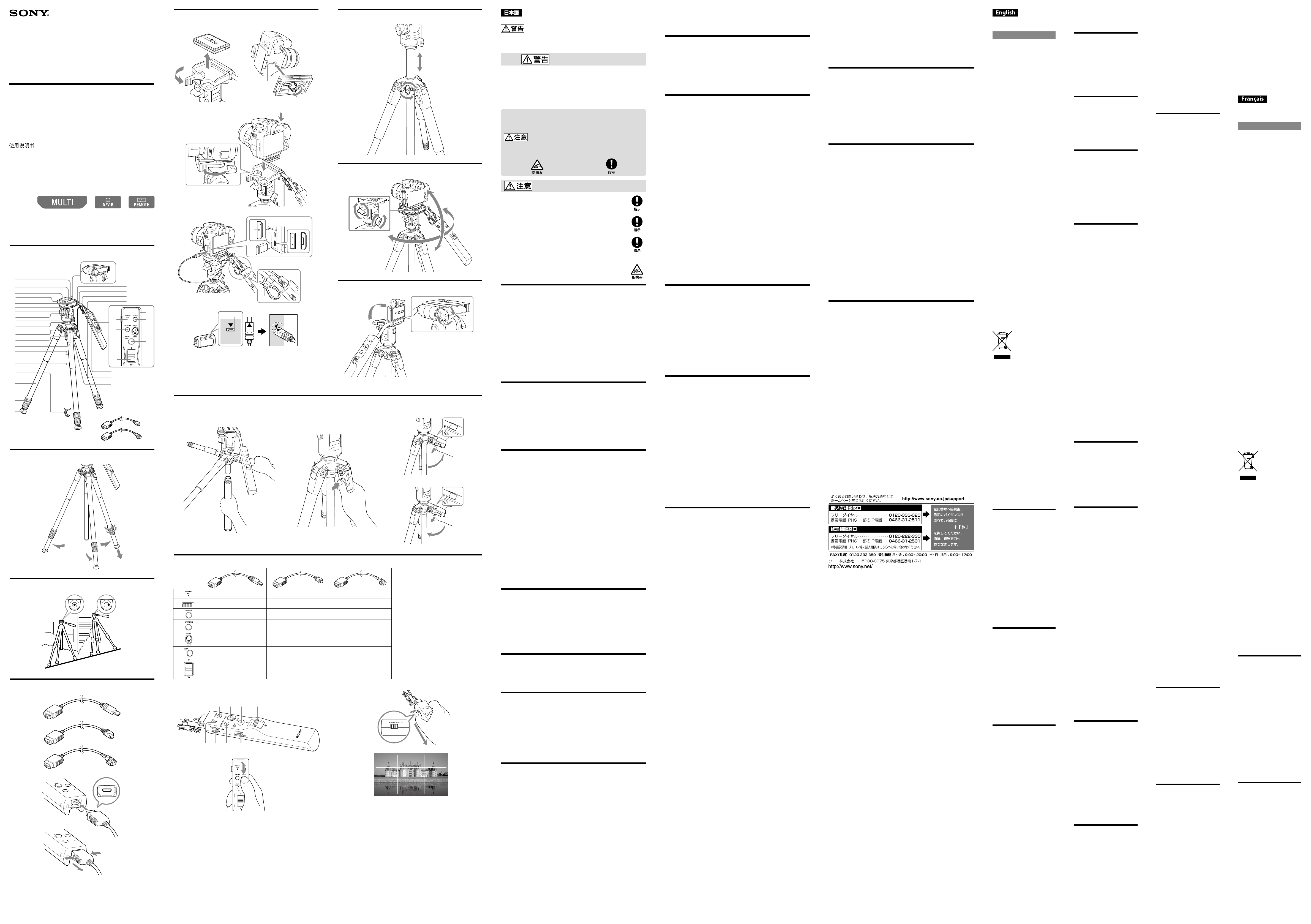
各部のなまえ
カメラネジ
1
ビデオボス
2
クイックシュー
3
クイックシュー固定レバー
4
シューベース
5
位置合わせマーク(カメラ台)
6
位置合わせマーク(雲台
BODY
)
7
ティルトストッパー
8
パンストッパー
9
ダンパーリング
10
エレベーターストッパー
11
脚角度調節ボタン
12
脚角度ストッパー
13
エレベーター
A
14
エレベーター
B
15
フック
16
脚
17
脚ロックナット
18
石突ゴム(スパイク付き)
19
パンハンドルストッパー
20
水準器
21
パンハンドル
22
コードクランパー
2
3
マ
ルチ端子用接続ケーブル
*
24
ストラップホール
25
POWER/REC
ランプ
26
POWER
ボタン
27
GRID LINE
ボタン
28
PHOTO
ボタン
29
START/STOP
ボタン
30
ズームレバー
31
SLOW ZOOM
スイッチ
32
PUSH RELEASE
ボタン
33
三脚ストラップホール
34
A/V
リモート端子用接続
35
ケーブル
REMOTE
(リモート)端子用
36
接続ケーブル
*
本機とマルチ端子用接続ケーブルとは、一体で梱包された状態にて出荷
されています。
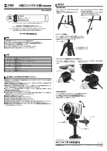
三脚を立てる
1
脚ロックナットを緩める。
2
希望の長さに脚を引き出す。
3
脚ロックナットを締め固定する。
4
脚を開く。
ご注意
三脚の脚はゆっくりと開いてください。強い力で引っ張ると故障の原因に
なります。
リングナットは緩めすぎると外れる場合がありますのでご注意ください。
水平の調整をする
水平の調整はエレベーターを下げた状態で行ってください。
1
位置合わせマーク(雲台
BODY
)と位置合わせマーク(カメラ台)を合わ
せ、ティルトストッパーを締める。
2
水準器の中の気泡が円の中に入るように、脚の長さを調整する。
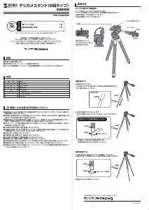
接続ケーブルを取り付ける
お使いのカメラに合った接続ケーブルを、リモコンに取り付けてくださ
い。
ご注意
上下方向に気をつけて、イラストのプラグ
ˎ
a
部をリモコンに接続してく
ださい。
取りはずすときにはプラグ部分を持って取りはずしてください。ケーブ
ˎ
ル部分を引っ張ると破損する恐れがあります。
本機とマルチ端子用接続ケーブルとは、一体で梱包された状態にて出荷
ˎ
されています。
カメラを取り付ける
バッテリーやメモリーカードなどは、カメラを三脚に取り付ける前にセッ
トしておいてください。
1
クィックシュー固定レバーを手前側に引きながら、クィックシューを
はずす。
2
クイックシューのビデオボスとカメラネジをカメラのボス穴
(a)
と三脚
用ネジ穴に合わせ、カメラネジをしっかり締める。
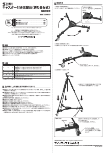
ご注意
ビデオカメラ以外のカメラでは、ビデオボスがカメラに干渉しない位
置で取り付けてください。
3
クイックシューを元の位置に差し込んで、カチッと音がするまで押し
下げる。
押し下げたあと、念のためクイックシュー固定レバーを奥側に押して
締め込んでください。
4
接続ケーブルの端子
(c)
をカメラの端子に接続する。
コードが長い場合は、コードクランパー
(b)
に挟んでください。
ご注意
マルチ端子には、正しい挿入方向があります。逆向きのまま無理に
ˎ
挿し込むと、本機およびカメラを破損することがありますのでご注
意ください。
カメラのマルチ端子は
2
種類あります。
ˎ
1
17
16
18
19
5
7
6
14
15
3
4
8
2
21
22
23
24
32
33
34
35
36
10
11
12
13
9
20
27
25
26
28
31
29
30
a b
11
2
1 2
a
3
4
c
b
MULTI
MULTI
d
1 3 4
5
A
SLOW ZOOM
ON OFF
Connecting cable for REMOTE 36
Terminal
* The tripod and the connecting cable
for Multi Terminal are included
together at the time of purchase.
Setting the Tripod
1 Unlock the leg length adjustment
locking nuts.
2 Adjust the length of the legs.
3 Tighten the leg length adjustment
lock nuts.
4 Spread the legs.
Caution
Spread the legs of the tripod slowly.
The legs may break if you pull them
too strongly.
Be careful not to loosen the ring nuts
too much or they may come off.
Adjusting the level
When adjusting the level, first lower
the elevator of the tripod.
1 Align the positioning mark on
the tripod head body with the
positioning mark on the tripod
head and tighten the tilt locking
lever.
2 Adjust the length of the legs so
that the air bubble in the level
stays in the circle.
Attaching the
connecting cable
Attach the adaptable connecting cable
of your camera to the terminal of the
Remote Commander.
Caution
Orientate plug “a” as illustrated ˎ
and insert it into the remote
commander.
Hold the plug when detaching the ˎ
cable. Pulling the cable itself could
damage the connector.
The tripod and the connecting cable ˎ
for Multi Terminal are included
together at the time of purchase.
Mounting the Camera
Install a battery pack, memory card,
etc. in the camera before mounting it
on the tripod.
1 While pulling the camera
mounting shoe lock lever fully
forward, slide the camera
mounting shoe from the tripod
head.
2 Align the pin and the camera
mounting screw of the camera
mounting shoe with the
positioning hole (a) and the screw
hole for the tripod. Then tighten
the camera mounting screw.
Caution
When attaching a camera other
than a video camera to the tripod,
position it so that it does not to
touch the pin for video cameras.
3 Push the camera mounting shoe
fully in until it clicks into place.
Then push the camera mounting
shoe lock lever to the back to
prevent the shoe from coming
out.
4 Connect the terminal of the
connecting cable (c) to the
terminal of the camera.
If the cable is too long, clamp the
cable with a cable clamper (b).
Caution
The multi connector must be ˎ
inserted the right way up. Be
careful not to connect it upside
down or you may damage the
tripod or camera.
There are two types of camera ˎ
multi terminal.
When connecting the ˎ
connecting cable for multi
terminal to the multi terminal
of the camera (shaped as in
(d)), align the mark on the
plug with the mark on the
multi terminal. Forcing the plug
in the wrong way round will
cause a malfunction.
Adjusting the Height
of the Elevator
1 Loosen the elevator lock lever.
2 Adjust the height by moving the
tripod head up or down.
3 Tighten the elevator lock lever.
Caution
Hold the tripod head when ˎ
unlocking the elevator lock lever
so that the tripod head does not
suddenly drop down.
After adjusting the height, firmly ˎ
tighten the elevator lock lever.
Panning and Tilting
Before panning and tilting, make sure
that the elevator lock lever is locked
firmly. If it is not locked firmly, the
camera will shake.
Panning
You can pan 360° when shooting
pictures.
1 Loosen the pan lock lever.
2 Adjust the position of the camera
by moving the pan handle left/
right.
3 Tighten the pan lock lever.
Caution
If you pan the camera suddenly,
the camera mounting screw could
become loose. Check the screw from
time to time to make sure that it is
not loose.
Tilting
You can tilt your camera up/down
when shooting pictures.
4 Loosen the tilt lock lever.
5 Adjust the position of the camera
by moving the pan handle up/
down.
6 Tighten the tilt lock lever.
Caution
This tripod has two separate ˎ
elevators for low position work.
If you raise the connection part
of elevator A, and elevator B from
the main unit and keep panning
counterclockwise during pan lock,
elevator A will come apart from
elevator B.
When panning with the elevator
raised, fasten elevator A and
elevator B tightly and be sure to
loosen the pan lock.
Do not adjust torque weight ˎ
using the pan lock lever or the tilt
lock lever. Doing so may cause a
malfunction. Do panning or tilting
after loosening each lock lever
properly.
Changing the Angle
of the Tripod Head
You can switch the tripod head from
a horizontal recording position to a
vertical recording position.
Loosen the pan handle lock lever,
stand the tripod head to the right,
then tighten the lever.
Caution
You may not be able to fix the ˎ
tripod head to your desired position
or the tripod may become unstable,
depending on the center of gravity
of the camera.
Stand and return the tripod head ˎ
slowly so that the camera is not hit.
After standing the tripod head, ˎ
firmly tighten the pan handle
locking lever.
Be careful not to loosen the pan ˎ
handle locking lever too much or
the pan handle may come off.
Setting the Degree of
Opening of the Legs
You can adjust the leg angle to 23, 50
or 75 degrees by raising the leg angle
locking lever.
To set the tripod in a low or
semi-low position
1 If the elevator touches the ground
in a low position, replace elevator
B beforehand.
2 Close the legs a little.
3 Press the leg angle adjustment
button.
4 Spread the legs while still pressing
the leg angle adjustment button.
5 At the desired angle, release the
leg angle adjustment button.
Then close the legs slightly until
the leg adjustment locking levers
return to their original position.
Caution
Without closing the legs slightly ˎ
first, the leg angle adjustment
button may be stiff and not move.
After adjusting the angle of the
legs, spread the legs until the leg
adjustment lock levers return to
their original position.
Push all surfaces of the leg angle ˎ
adjustment button.
If you use the tripod in a low or ˎ
semi-low position, do not extend
the legs or the tripod may become
unstable.
When using the tripod in a low ˎ
position, make sure the Remote
Commander does not touch the
ground.
Using the Remote
Commander
Also see the operating instructions of
your camera.
The usable buttons, switches and
lamps vary depending on the
connecting cable used (A).
: Valid (Note: May be invalid with
some cameras)
: Invalid
Turning on the power
1 Turn on the power of the camera
and set it to standby mode.
The POWER/REC lamp (e) of
the Remote Commander lights
in green.
2 Set the camera to the movie or
still image mode.
Caution
If you leave the camera in standby
mode for a while, the camera turns
off automatically. To resume standby
mode, turn on the camera, pressing
the POWER button (a) of the Remote
Commander.
To record a moving image
Press the START/STOP button (c).
The POWER/REC lamp lights in red
and recording starts.
To stop recording, press the START/
STOP button again.
The POWER/REC lamp lights in
green. The camera is set to standby
mode.
To record a still image
Half-press the PHOTO button (b) to
bring the camera into focus, and then
press the button all the way.
Locking function (B)
During bulb shooting or continuous
shooting, you can set the PHOTO
button so that it is held down.
With the PHOTO button fully pressed
down, slide it in the direction of the
arrow.
When the PHOTO button is locked ˎ
during bulb shooting, the shutter
is open.
When the PHOTO button is locked ˎ
during continuous shooting, the
shutter continues to open and close.
Caution
Not all cameras support bulb ˎ
shooting or continuous shooting.
See the operating instructions of
your camera for details.
Do not press the PHOTO button ˎ
with excessive force or the Remote
Commander may break.
Do not leave the PHOTO button ˎ
locked.
Detaching Remote Commander
(C)
When shooting still photos, you can
prevent camera shake by detaching
the remote commander from the
tripod before pressing the PHOTO
button.
To detach the Remote Commander,
pull it out while holding the tripod
and pressing the PUSH RELEASE
button (f).
To attach the remote commander,
slowly slide the remote commander
on while holding the tripod until the
PUSH RELEASE button (f) clicks out.
Zooming
Tilt the zoom lever (d).
T side (telephoto): Subject appears
closer.
W side (wide angle): Subject appears
farther away.
The zooming speed changes
depending on the angle of zoom lever
when you tilt it.
Slow zooming
Set the SLOW ZOOM switch (h) to
ON.
Regardless of the tilt angle of zoom
lever, zooming is always performed at
slow speed.
To cancel the slow zooming function,
set the SLOW ZOOM switch to OFF.
Caution
The slow zooming speed varies ˎ
depending on a camera.
When the POWER/REC lamp ˎ
flashes in red, a warning message
is displayed on the camera. Check
the message on the screen of the
camera.
To display the grid line (D)
Press the GRID LINE button (g).
A horizontal/vertical grid line appears
on the camera screen.
Adjust the legs of the tripod and tilt
angle of your camera in accordance
with the grid line.
You can choose multiple grid lines
depending on your camera model.
You can set the grid lines by pressing
the GRID LINE button.
See the operating instructions of your
camera for details.
To cancel the grid line display, press
the GRID LINE button until the grid
line display turns off.
The photograph is just an example *
of the screen. The actual screen to be
displayed may be different.
After recording
Press the POWER button of the
Remote Commander to turn off the
camera.
Folding the Tripod
1 Remove the camera from the
tripod.
2 Loosen the pan lock lever and tilt
lock lever and fold down the pan
handle.
3 Tighten the pan lock lever and tilt
lock lever.
4 Loosen the leg length adjustment
lock lever of the three legs and
fold the legs.
5 Tighten the leg length adjustment
lock lever to hold the legs in
place.
Carrying the tripod
Make sure to carry the tripod in its
carrying case.
Caution
Never carry the tripod with the
camera attached to it.
Specifications
Maximum load
4 kg (8 lbs. 13 oz.)
Panning angle
360 degrees
Tilting angle
90 degrees down, 70 degrees up
Leg extension
Each leg has 3 telescoping shafts.
Remote Commander functions
POWER button, PHOTO button,
START/STOP button, zoom
lever (T/W), GRID LINE button,
PUSH RELEASE button, SLOW
ZOOM switch
Dimensions
Maximum height:
Approx. 1 700 mm (67 inches)
(Legs spread at 23 degrees)
Minimum height:
Approx. 670 mm (26 1/2 inches)
Remote Commander cable length
Approx. 800 mm (31 1/2 inches)
Pan handle length
Approx. 260 mm (10 1/4 inches)
Elevator stroke
Approx. 390 mm (15 3/8 inches)
Operating temperature range
0°C to 40°C (32°F to 104°F)
Mass
Approx. 2.1 kg (4 lbs. 10 oz.)
Supplied accessories
Carrying case (1)
Connecting cable for Multi
Terminal (1)
Connecting cable for A/V
Remote Terminal (1)
Connecting cable for REMOTE
Terminal (1)
Set of printed documentation
Design and specifications are subject
to change without notice.
Avant de faire fonctionner ce produit,
lisez attentivement ce mode d’emploi
et conservez-le pour toute référence
ultérieure.
AVERTISSEMENT
Pour réduire les risques d’incendie ou
d’électrocution,
1) n’exposez pas l’appareil à la pluie ou
à l’humidité ;
2) ne placez pas d’objets remplis de
liquides (vases, etc.) sur l’appareil.
Cet appareil a été testé et jugé
conforme aux limites établies par
la Réglementation EMC visant
l’utilisation de câbles de raccordement
de moins de 3 mètres.
À l’intention des clients aux
É.-U.
AVERTISSEMENT :
Par la présente, vous êtes avisé du
fait que tout changement ou toute
modification ne faisant pas l’objet
d’une autorisation expresse dans le
présent manuel pourrait annuler votre
droit d’utiliser l’appareil.
Note :
L’appareil a été testé et est
conforme aux exigences d’un
appareil numérique de Classe B,
conformément à la Partie 15 de la
réglementation de la FCC.
Ces critères sont conçus pour fournir
une protection raisonnable contre
les interférences nuisibles dans un
environnement résidentiel. L’appareil
génère, utilise et peut émettre
des fréquences radio; s’il n’est pas
installé et utilisé conformément aux
instructions, il pourrait provoquer
des interférences nuisibles aux
communications radio.
Cependant, il n’est pas possible de
garantir que des interférences ne
seront pas provoquées dans certaines
conditions particulières. Si l’appareil
devait provoquer des interférences
nuisibles à la réception radio ou à la
télévision, ce qui peut être démontré
en allumant et éteignant l’appareil,
il est recommandé à l’utilisateur
d’essayer de corriger cette situation
par l’une ou l’autre des mesures
suivantes :
Réorienter ou déplacer l’antenne –
réceptrice.
Augmenter la distance entre –
l’appareil et le récepteur.
Brancher l’appareil dans une prise –
ou sur un circuit différent de celui
sur lequel le récepteur est branché.
Consulter le détaillant ou un –
technicien expérimenté en radio/
téléviseurs.
Le câble d’interface fourni doit être
utilisé avec l’appareil pour satisfaire
les limites relatives à un dispositif
numérique conformément à la Sous
partie B de l’article 15 du Règlement
de la FCC.
Pour les clients en Europe
Traitement des appareils
électriques et électroniques en fin
de vie (Applicable dans les pays de
l’Union Européenne et aux autres
pays européens disposant de
systèmes de collecte sélective)
Ce symbole, apposé sur le produit
ou sur son emballage, indique que
ce produit ne doit pas être traité avec
les déchets ménagers. Il doit être
remis à un point de collecte approprié
pour le recyclage des équipements
électriques et électroniques. En vous
assurant que ce produit sont mis
au rebut de façon appropriée, vous
participez activement à la prévention
des conséquences négatives que
leur mauvais traitement pourrait
provoquer sur l’environnement et
sur la santé humaine. Le recyclage
des matériaux contribue par ailleurs
à la préservation des ressources
naturelles. Pour toute information
complémentaire au sujet du recyclage
de ce produit, vous pouvez contacter
votre municipalité, votre déchetterie
locale ou le point de vente où vous
avez acheté le produit.
Avis aux consommateurs des pays
appliquant les Directives UE
Ce produit a été fabriqué par ou pour
le compte de Sony Corporation, 1-7-1
Konan Minato-ku Tokyo, 108-0075
Japon. Toutes les questions relatives à
la conformité des produits basées sur
la législation européenne doivent être
adressées à son représentant, Sony
Deutschland GmbH, Hedelfinger
Strasse 61, 70327 Stuttgart,
Allemagne.
Pour toute question relative au
Service Après-Vente ou à la Garantie,
merci de bien vouloir vous référer
aux coordonnées qui vous sont
communiquées dans les documents «
Service (SAV) » ou Garantie.
Précautions d’emploi
Retrait de la caméra
Veillez à bien retenir la caméra
lorsque vous la retirez. Le sabot
de montage de caméra se détache
automatiquement du trépied lorsque
vous dévissez le levier de blocage du
sabot de montage de caméra, de sorte
que la caméra risque de tomber, si
vous ne la retenez pas.
Transport du trépied
Après avoir utilisé le trépied, ˎ
déposez la caméra, fermez les
pieds et remettez la poignée de
pan dans sa position d’origine.
Ne transportez jamais le trépied ˎ
avec la caméra rattachée.
Nettoyage
Quand le trépied est sale, essuyez-le ˎ
avec un chiffon doux légèrement
imprégné d’une solution détergente
faible. Puis, essuyez le trépied avec
un chiffon sec.
Après avoir utilisé le trépied à la ˎ
plage ou à un endroit exposé aux
embruns marins, nettoyez-le avec
un chiffon sec.
Caractéristiques
Le VCT-VPR10 est un trépied
présentant des fonctions de
télécommande pour appareils photo/
caméscopes.
Vous pouvez utiliser la ˎ
télécommande dans la poignée
de pan pour piloter les caméras
pourvues d’une multiprise, d’une
prise de commande à distance A/V
et d’une prise REMOTE Sony. Ce
trépied peut ne pas être compatible
avec toutes les caméras. Veuillez
consulter le site de Sony pour les
modèles compatibles.
Les fonctions de la télécommande ˎ
comprennent les fonctions
essentielles d’enregistrement
(POWER ON/OFF, enregistrement
de films/photos et zooming), et
aussi les fonctions SLOW ZOOM
ON/OFF et d’affichage de la grille
ON/OFF.
Mouvement horizontal et vertical ˎ
régulier avec la poignée de rotation
horizontale/verticale à cylindre
hydraulique.
Before operating the product, please
read this manual thoroughly and
retain it for future reference.
WARNING
To reduce the risk of fire or electric
shock,
1) do not expose the unit to rain or
moisture.
2) do not place objects filled with
liquids, such as vases, on the
apparatus.
This product has been tested and
found compliant with the limits set
out in the EMC regulation for using
connection cables shorter than 3
meters.
For Customers in the U.S.A.
CAUTION
You are cautioned that any changes or
modifications not expressly approved
in this manual could void your
authority to operate this equipment.
Note:
This equipment has been tested and
found to comply with the limits for
a Class B digital device, pursuant to
Part 15 of the FCC Rules.
These limits are designed to provide
reasonable protection against
harmful interference in a residential
installation. This equipment
generates, uses, and can radiate
radio frequency energy and, if not
installed and used in accordance
with the instructions, may cause
harmful interference to radio
communications. However, there is
no guarantee that interference will
not occur in a particular installation.
If this equipment does cause harmful
interference to radio or television
reception, which can be determined
by turning the equipment off and
on, the user is encouraged to try to
correct the interference by one or
more of the following measures:
Reorient or relocate the receiving –
antenna.
Increase the separation between the –
equipment and receiver.
Connect the equipment into –
an outlet on a circuit different
from that to which the receiver is
connected.
Consult the dealer or an –
experienced radio/TV technician
for help.
The supplied interface cable must be
used with the equipment in order to
comply with the limits for a digital
device pursuant to Subpart B of Part
15 of FCC Rules.
For the Customers in Europe
Disposal of Old Electrical &
Electronic Equipment (Applicable
in the European Union and other
European countries with separate
collection systems)
This symbol on the product or on
its packaging indicates that this
product shall not be treated as
household waste. Instead it shall
be handed over to the applicable
collection point for the recycling of
electrical and electronic equipment.
By ensuring this product is disposed
of correctly, you will help prevent
potential negative consequences for
the environment and human health,
which could otherwise be caused
by inappropriate waste handling
of this product. The recycling of
materials will help to conserve
natural resources. For more detailed
information about recycling of this
product, please contact your local
Civic Office, your household waste
disposal service or the shop where
you purchased the product.
Notice for the customers in the
countries applying EU Directives
The manufacturer of this product
is Sony Corporation, 1-7-1 Konan
Minato-ku Tokyo, 108-0075 Japan.
The Authorized Representative for
EMC and product safety is Sony
Deutschland GmbH, Hedelfinger
Strasse 61, 70327 Stuttgart, Germany.
For any service or guarantee matters
please refer to the addresses given
in separate service or guarantee
documents.
Precautions on Use
Removing the camera
Make sure that you hold on to the
camera when removing it. The
camera mounting shoe automatically
comes off the tripod when you unlock
the camera mounting shoe lock lever,
so the camera may fall, if you are not
holding it.
Carrying the tripod
After using the tripod, ˎ remove
the camera, close the legs and
replace the pan handle to the
original position.
Never carry the tripod with the ˎ
camera attached.
Cleaning
When the tripod becomes dirty, ˎ
clean it with a soft cloth lightly
moistened with a mild detergent
solution. Then, wipe the tripod
clean with a dry cloth.
After using the tripod on the beach ˎ
or in places subject to sea breezes,
wipe it clean with a dry cloth.
Features
VCT-VPR10 is a tripod provided with
Remote Commander functions for
cameras.
You can use the built-in Remote ˎ
Commander in the pan handle to
operate cameras that are equipped
with the Sony Multi Terminal, A/V
Remote Terminal, and REMOTE
Terminal. This tripod may not
be compatible with all cameras.
Please visit the Sony website for the
compatible models.
The Remote Commander functions ˎ
include basic recording functions
(POWER ON/OFF, video/still
image recording and zooming) and
also SLOW ZOOM ON/OFF and
grid line display ON/OFF functions.
Smooth panning/tilting with an oil- ˎ
cylinder pan/tilt handle.
Identifying the Parts
Camera mounting screw1
Pin2
Camera mounting shoe3
Camera mounting shoe lock 4
lever
Shoe base5
Positioning mark (Tripod head)6
Positioning mark (Tripod head 7
body)
Tilt lock lever8
Pan lock lever9
Damper ring10
Elevator lock lever11
Leg angle adjustment button12
Leg angle locking lever13
Elevator A14
Elevator B15
Hook16
Leg17
Leg length adjustment locking 18
nut
Rubber feet (with spikes)19
Pan handle lock lever20
Level21
Pan handle22
Cable clamper23
Connecting cable for Multi 24
Terminal*
Strap hole25
POWER/REC lamp26
POWER button27
GRID LINE button28
PHOTO button29
START/STOP button30
Zoom lever31
SLOW ZOOM switch32
PUSH RELEASE button33
Tripod strap hole34
Connecting cable for A/V 35
Remote Terminal
(Suite à la page arrière)
B
a b c d
f g h
e
C
1
2
D *
お使いのカメラによってはグリッドラインを複数種類選択できます。
GRID LINE
ボタンを押すたびに切り替えることができます。
詳しくはカメラの取扱説明書をご参照ください。
グリッドライン表示を解除するには、表示が消えるまで
GRID LINE
ボ
タンを押してください。
写真はイメージです。実際の画面表示とは異なります。
*
撮影が終わったら
リモコンの
POWER
ボタンを押して電源を切る。
三脚をたたむ
1
三脚からカメラをはずす。
2
パンストッパー、ティルトストッパーを緩めて、パンハンドルをたた
む。
3
パンストッパー、ティルトストッパーを締める。
4
3
本の脚の脚ロックナットを緩めて、脚をたたむ。
5
脚ロックナットを締めて固定する。
持ち運びについて
キャリングケースに入れてください。
ご注意
カメラを取り付けたままで、持ち運ばないでください。
主な仕様
積載カメラ重量
4 kg
以下
パンニング角
360
度
ティルティング角
前傾
90
度、後傾
70
度
脚段数
3
段
リモコン機能
POWER
ボタン、
PHOTO
ボタン、
START/STOP
ボタン、ズームレバー(
T/W
)、
GRID LINE
ボタン、
PUSH RELEASE
ボタン、
SLOW ZOOM
スイッチ
外形寸法
全高
約
1 700mm
(開脚角度
23
度)
縮長
約
670mm
、
接続ケーブルの長さ
約
800mm
パンハンドルの長さ
約
260mm
エレベータースライド
約
390mm
使用温度範囲
0
℃
〜
40
℃
質量
約
2.1 Kg
付属品
キャリングケース(
1
個)、
マルチ端子用接続ケーブル(
1
本)
A/V
リモート端子用接続ケーブル(
1
本)
REMOTE
(リモート)端子接続ケーブル(
1
本)
印刷物一式
仕様および外観は、改良のため予告なく変更することがあります。
保証書とアフターサービス
保証書
この製品には保証書が添付されていますので、お買い上げの際、お受け
ˎ
取りください。
所定事項の記入および記載内容をお確かめのうえ、大切に保管してくだ
ˎ
さい。
保証期間は、お買い上げ日より
1
年間です。
ˎ
アフターサービス
調子が悪いときはまずチェックを
この取扱説明書をもう一度ご覧になってお調べください。
それでも具合の悪いときは
ソニーの相談窓口にご相談ください。
保証期間中の修理は
保証書の記載内容に基づいて修理させていただきます。詳しくは保証書を
ご覧ください。
保証期間経過後の修理は
修理によって機能が維持できる場合は、ご要望により有料修理させていた
だきます。
部品の保有期間について当社ではリモコン三脚の補修用性能部品(製品の
機能を維持するために必要な部品)を、製造打ち切り後
8
年間保有していま
す。ただし、故障の状況その他の事情により、修理に代えて製品交換をする
場合がありますのでご了承ください。
ご相談になるときは次のことをお知らせください。
型名:
ˎ
VCT-VPR10
故障の状態:できるだけ詳しく
ˎ
お買い上げ年月日
ˎ
「400」
2
1
3
1
6
5
2
4
3

Loading…
評価
ソニー VCT-VPR10 三脚について、製品の評価を入力し、お客様のお考えをお教えてください。この製品とのお客様の経験を共有したいですか、または質問したいですか。ページ下部にコメントを入力してください。このマニュアルの詳細
ソニー VCT-VPR10 三脚 に紙のマニュアルがあると便利だと理解しています。 マニュアルは当社 Web サイトからいつでもダウンロードして、ご自身で印刷していただけます。 オリジナルのマニュアルが必要な場合は、Sony にお問い合わせいただくことをお勧めします。 オリジナルのマニュアルを提供してくれるかもしれません。 ソニー VCT-VPR10 三脚 の別の言語のマニュアルをお探しですか? 当社のホームページでご希望の言語を選択し、モデル番号を検索して入手可能かどうかを確認してください。
仕様
| メーカー | Sony |
| モデル | VCT-VPR10 |
| カテゴリー | 三脚 |
| ファイルの種類 | |
| ファイルサイズ | 0.91 MB |


この商品に関する会話に参加する
ここでは、ソニー VCT-VPR10 三脚 についての意見を共有できます。 疑問がある場合は、まず説明書をよく読んでください。 マニュアルのご請求は、お問い合わせフォームより承ります。